
Key Points:
-
Time lags between storm sudden commencement and scintillation detections by ground-based Global Navigation Satellite System receivers at northern auroral latitudes were surveyed
-
The time lags varied with geomagnetic latitude and magnetic local time of satellite-receiver line-of-sight signal paths assumed at ionospheric piercing points
-
Shorter time lag was detected by the observations close to aurora cusp as well as those on the nightside at the storm onset


Z. Yang, J. Morton, I. Zakharenkova, I. Cherniak, S. Song, W. Li (2020), Global View of Ionospheric Disturbances Impacts on Kinematic GPS Positioning Solutions during the 2015 St Patrick’s Day Storm. Journal of Geophysical Research: Space Physics. DOI: 10.1029/2019JA027681
Key Points:
-
Ionospheric disturbances caused high-precision GPS positioning degradation on a global scale during the 2015 St Patrick’s Day storm;
-
At high latitudes, severe position degradation was observed around magnetic noon and midnight coinciding with plasma irregularities zone;
-
At low latitudes, position errors were due to storm-induced plasma bubbles, EIA enhancement, and travelling ionospheric disturbances;
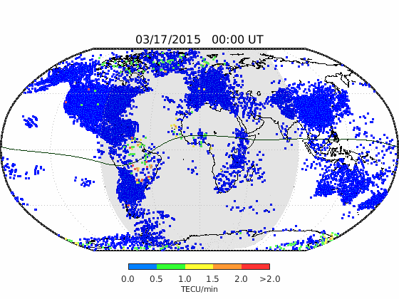

Two-dimensional maps of ionospheric plasma irregulariteis on 17-18 March 2015

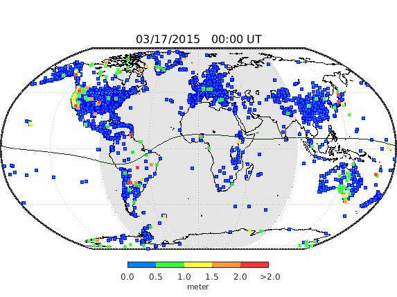
Two-dimensional maps of GPS Positioning error on 17-18 March 2015
Z. Yang, J. Morton (2020), Low-Latitude GNSS Ionospheric Scintillation Dependence on Magnetic Field Orientation and Impacts on Positioning. Journal of Geodesy. DOI: 10.1007/s00190-020-01391-7

Figure 1. (a) Illustration showing the progression of the geometry between the Earth’s magnetic field vector at ionospheric pierce points (IPPs) and the line-of-sight signal. The red arrow represents the IPP trajectory vector. represents the angle between and ; (b) Diagram showing the angle, the magnetic field vector , and the signal propagation direction. I and D are magnetic inclination and declination, respectively. Azi and Ele represent the azimuth and elevation of LOS at IPPs, respectively.

Figure 6. Sky plots of (a) MEO, (b) IGSO and GEO satellites observed with amplitude scintillations in the period of 19:00 to 03:00 LT; Their signal propagation directions are denoted in the color bar; C01, C02, C03 and C04 represent BDS GEO satellites. (c) Distributions of and scintillation occurrences as a function of the azimuth of the MEO, GEO, and IGSO satellites.
